This is the capstone design project I conducted for the course ME 450 at the University of Michigan. My collaborators on this project are Tiantian Li, Junjie Luo, and Haoze Hu.
Goal
The goal of project “Glovebox Pressure Control System for Redox Flow Battery” is to develop a pressure sensing and control system that will maintain the pressure of a glovebox between variable set limits with automated gas inlet/exit valves. This system is intended to help the Kwabi lab at the University of Michigan create a platform for the testing of novel chemistries for redox-flow batteries that are sensitive to atmosphere.
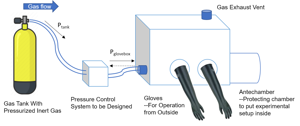 Schematic of the glovebox with key components labeled.
Requirements & Engineering Specifications
Relevant information was collected from various sources including literature review, benchmarking products and interviews with researchers from the Kwabi lab. The requirements and engineering specifications of the pressure sensing and control system are thus extrapolated and can be categorized into operation, safety and user related requirements. Key challenges of this project lie in the high-accuracy and high-resolution (±0.1 mbar) sensing and regulating of pressure in a low range of 0 – 20 mbar.
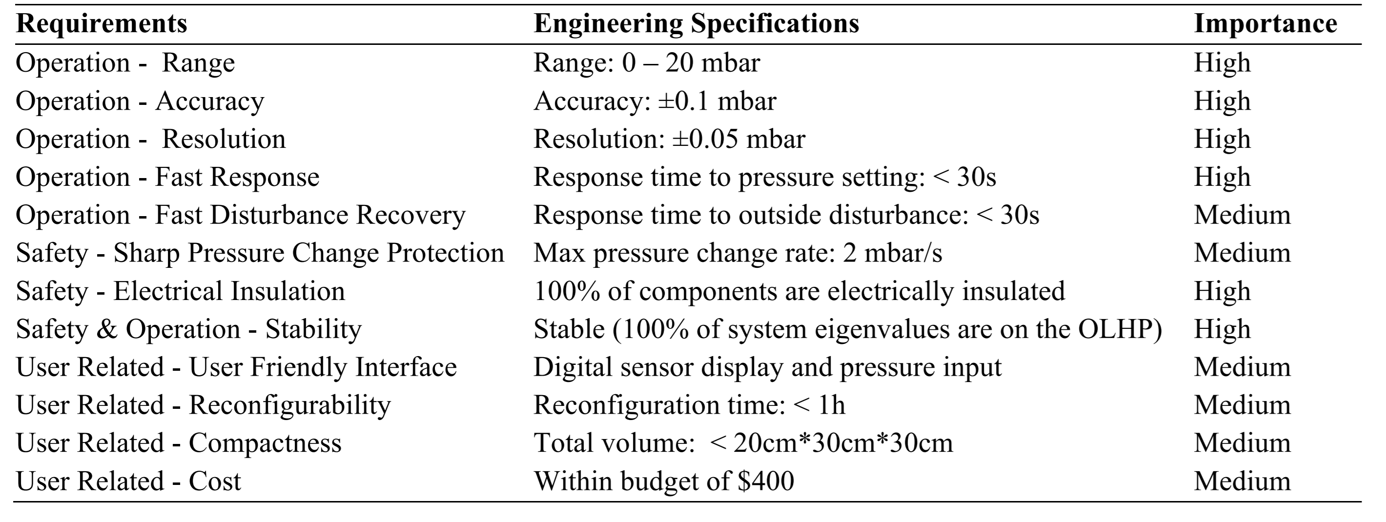 The requirements and their corresponding importance as well as engineering specification associated with the glove box pressure control system.
Concept Generation
Concepts generation process used two major methods, concept map and physical decomposition. Concept map helped incorporate broad aspects around the pressure control goal. Influencing aspects are connected and different traits of aspects are distinguished with colors. One important part of the concept map is the actuation methods to control the pressure. From the ideal gas law, pressure control can be changed with the amount of gas, volume and temperature. From these three directions, three concepts are developed. Physical decomposition helped break the complex systems into separate subsystems, including sensor, control, power and actuation. Actuation system are decomposed for each concept. These concepts are then evaluated with a Pugh chart, and the method to control the inflow and outflow of the gas with electronic valves are selected as the final solution with its high feasibility and potentially low cost.
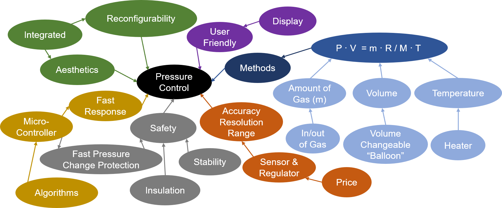 Concept map of the pressure control system. Different influential aspects are distinguished with colors, and the methods leads to three directions of concepts.
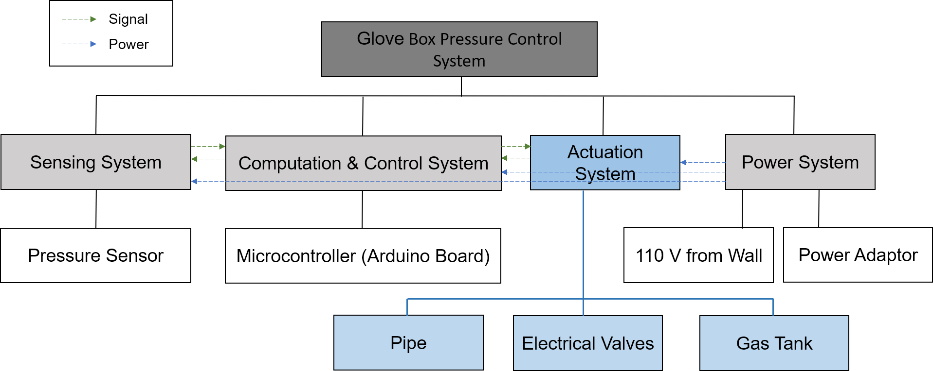 Physical decomposition of the system that controls the inflow and outflow of gas with electrical valves.
Final Design
Our final design uses electric valves (flow coefficients Cv = 0.08 & 0.6) to control the gas in flow and out flow, and an on-off feedback control algorithm was performed using a pressure sensor and the Arduino board. Through engineering analysis, formula was generated to simulate the system behavior, which were used to select the flow coefficients of the electric valves and verify the engineering specifications.
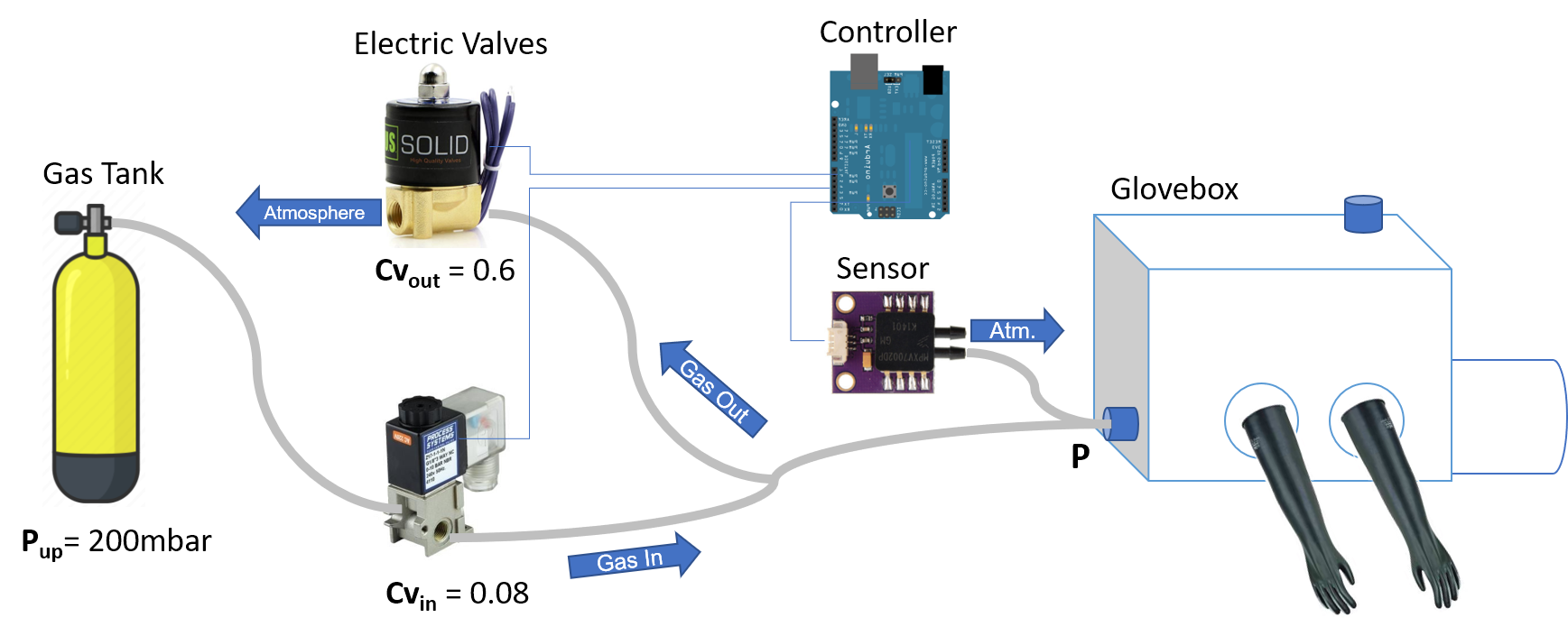 Illustration of the components of the final design solution.
General Validation Process
A full validation plan was developed for physical prototypes, and key specifications were validated virtually through performance simulation, including the disturbance rejection induced from glove movement volume change.
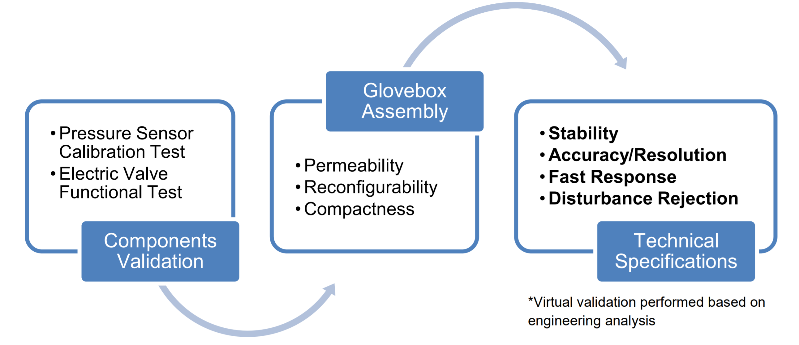 Validation Process Chart. Pressure controlling components are first validated with their functions and then assembled to the glovebox to verify the specifications and validate its functions.
Performance (by simulation)
The system was able to meet the specifications under reasonably slow glove movements.
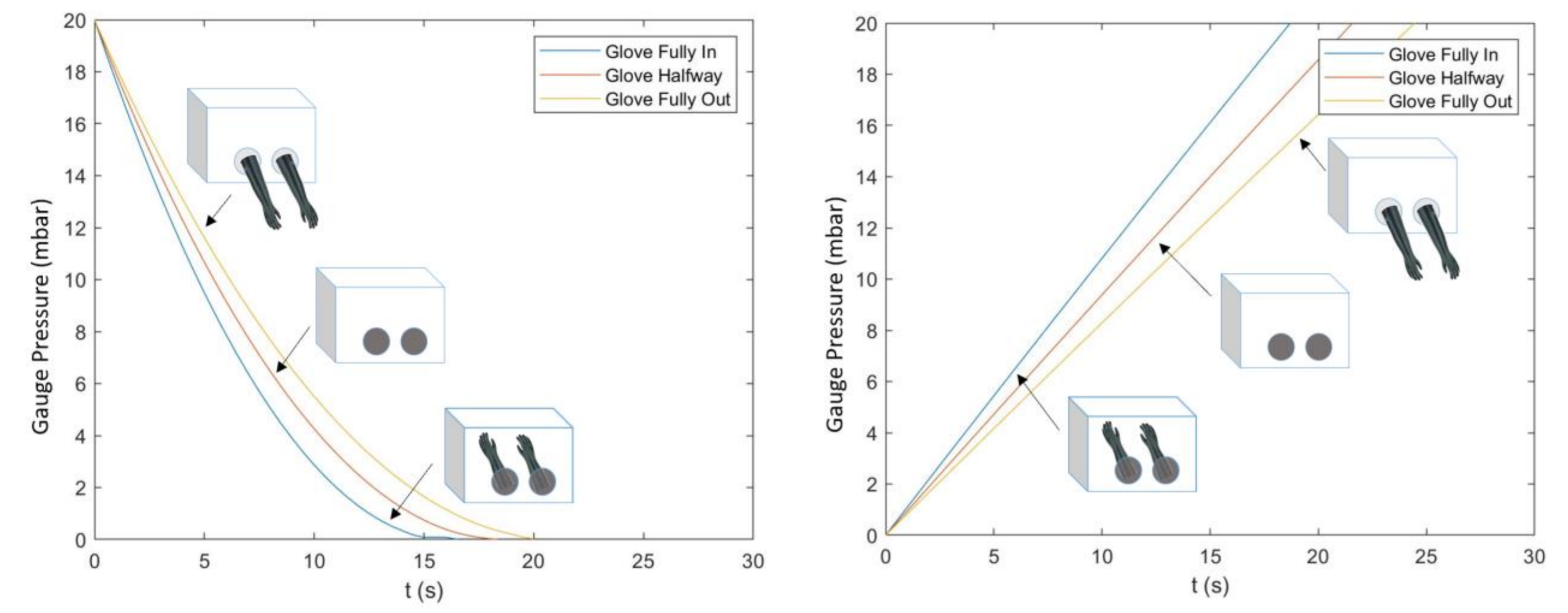 Simulation of maximum possible pressure change (20 mbar) for both the gas inflow (left) and outflow (right) cases at different glove box volumes. The simulation results show that the pressure changes more quickly at smaller volumes.
Future Improvements
In order to achieve faster glove movements, necessary improvements may be made to the system. There are two potential methods to solve this problem. The first method is to use an electric valve with changeable Cv value. When the difference between the current pressure and the desired pressure is big, the electric valve will work at high Cv value. As the current pressure is approaching the desired value, Cv value will be correspondingly decreasing to less than 0.1 for stability and accuracy. Accordingly, the program should be improved to control Cv value in real time based on the difference between the current pressure and the desired pressure. Although the electric valve with changeable Cv value works better, it costs much more.
If budget is limited, the second method can be considered: adding a pump to the pressure control system. The purpose of the pump is similar to what is discussed in the first method. When the difference between the current pressure and the desired pressure is large, the pump will be turned on to accelerate gas absorption/exhaustion. When the current pressure is close to the desired pressure, the pump will be shut down for stability and accuracy. Also, the program should be improved to control the pump in real time based on the difference between the current pressure and the desired pressure. In this case, the pump’s delay time should also be considered in the program. Compared with the former one, this method is cheaper, but the circuit will be more complex, and more parameters are introduced to the system (the pump’s delay time).
Conclusions
In general, this project achieves the pressure control function available in advanced and expensive glovebox workstations, which is built upon regular glovebox containers with a relatively low cost. It is a useful solution for the labs who need pressure-controlled testing environment but have restricted budgets.
Acknowledgements
We want to express our great appreciation to all those who contributed to the success of this project, including the team 09 members, our classmates in Section 05 who offered us useful suggestions, Heather and other Professors of ME 450 who taught us valuable knowledge and supported us, Professor Kaviany who met with us weekly to guide and help us, as well as Professor Kwabi and Mr. Modak who offered us this opportunity to work on the project and provided us with wonderful advises and questions along the way. Thank you very much for your help and it has been a pleasure working with you.