This is a student team project I joined for two years when I was at the University of Michigan. The student project team was called the M-Fly Student Aero Design Team. It was a fun, strong and passionate team where we collaborated well in an organized manner.

The following are the two aircrafts that I was mainly involved in designing during my two years on the team.
I worked on the M-11 as a member of the aerodynamics team of the aircraft, where I mostly learned and worked with Forster Guo, the aerodynamics lead at that time.
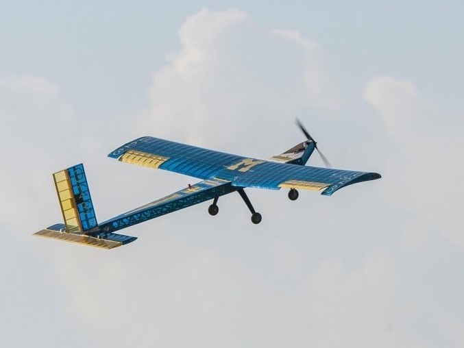 M-11
M-11
 M-11
M-11
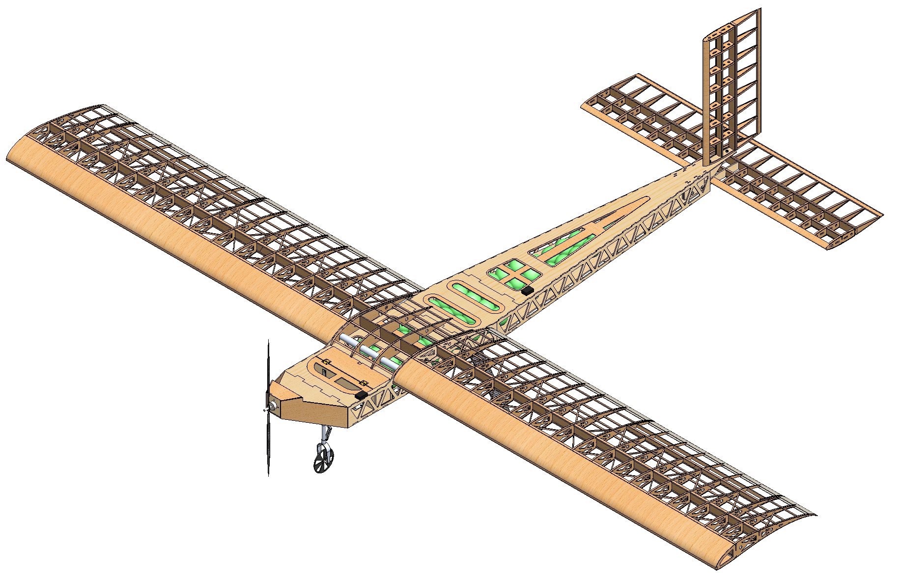
During my second year on the team, I was elected as the aerodynamics lead for the M-12. Therefore, I taught and led a sub-team to design the aerodynamics aspects of this new plane throughout the year.
 M-12
M-12
 M-12
M-12
 M-12
M-12
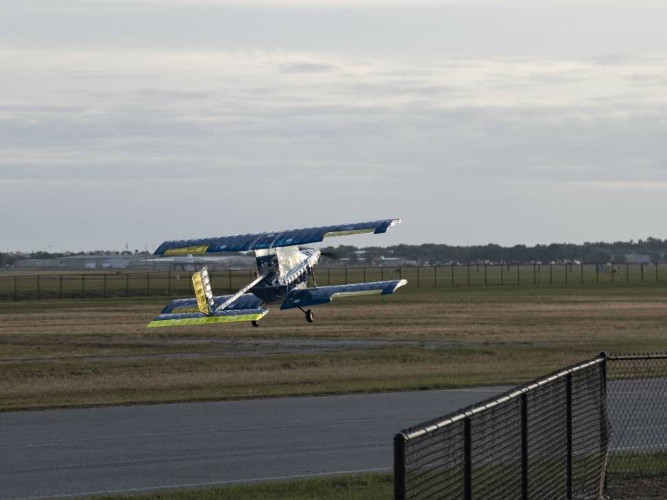
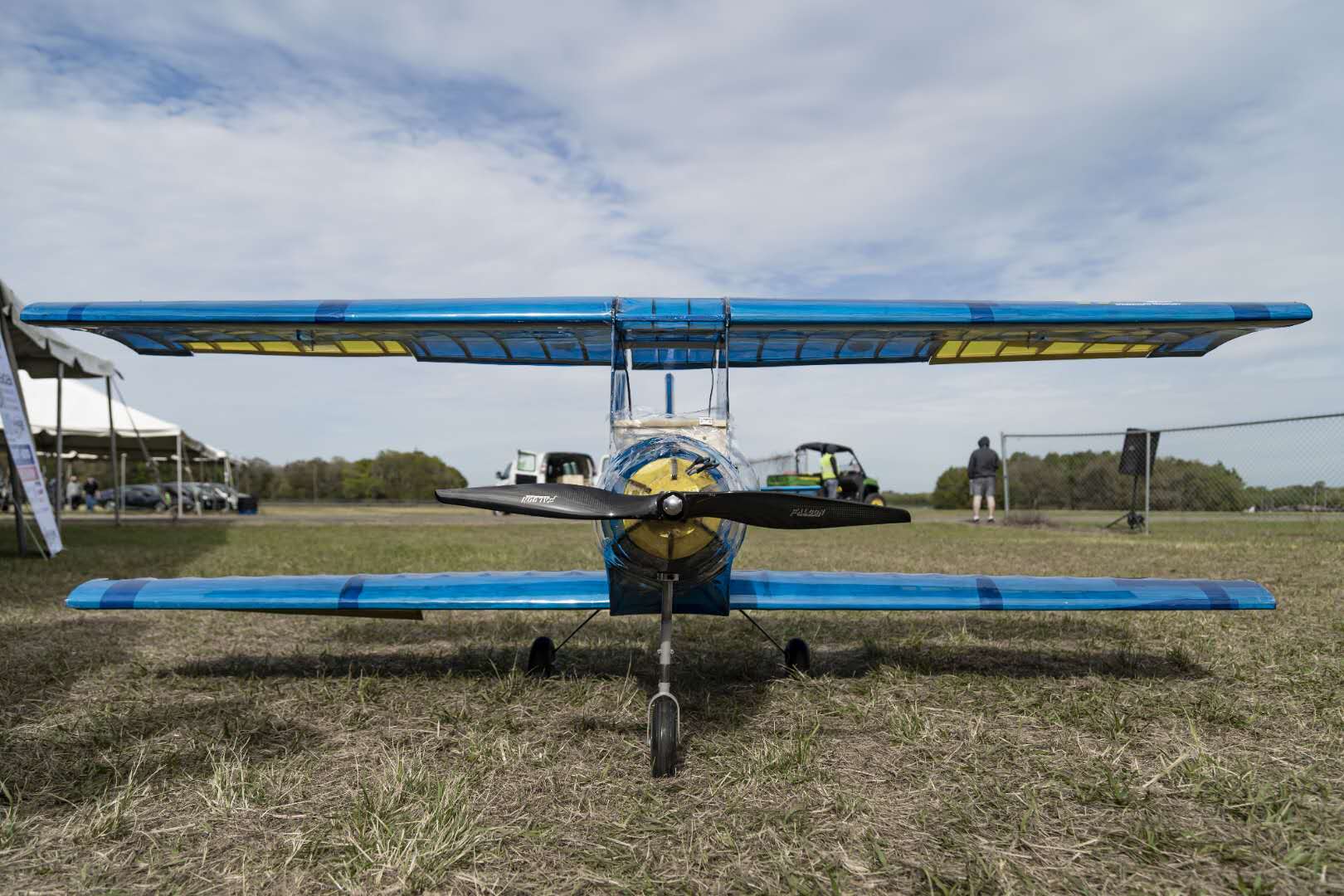
I am going to introduce the aerodynamics design of the M-12 below since this is the aircraft that I am mostly responsible for and spent the most time on as well. This is also the first biplane at this size on the team’s history as well! We were all excited that it successfully flew a few rounds during the 2020 SAE Aero Design East competition in Lakeland, FL.
Goal
Critical to M-Fly’s performance at SAE Aero Design East 2020 is the ability of the M-12 to record three flight rounds carrying 22 lbs of boxed payload and one spherical payload. Additionally critical to the team’s success is its ability to score within the top five teams in the design report and presentation respectively to maintain competitiveness with the other teams.
Overall Design Layout & Size
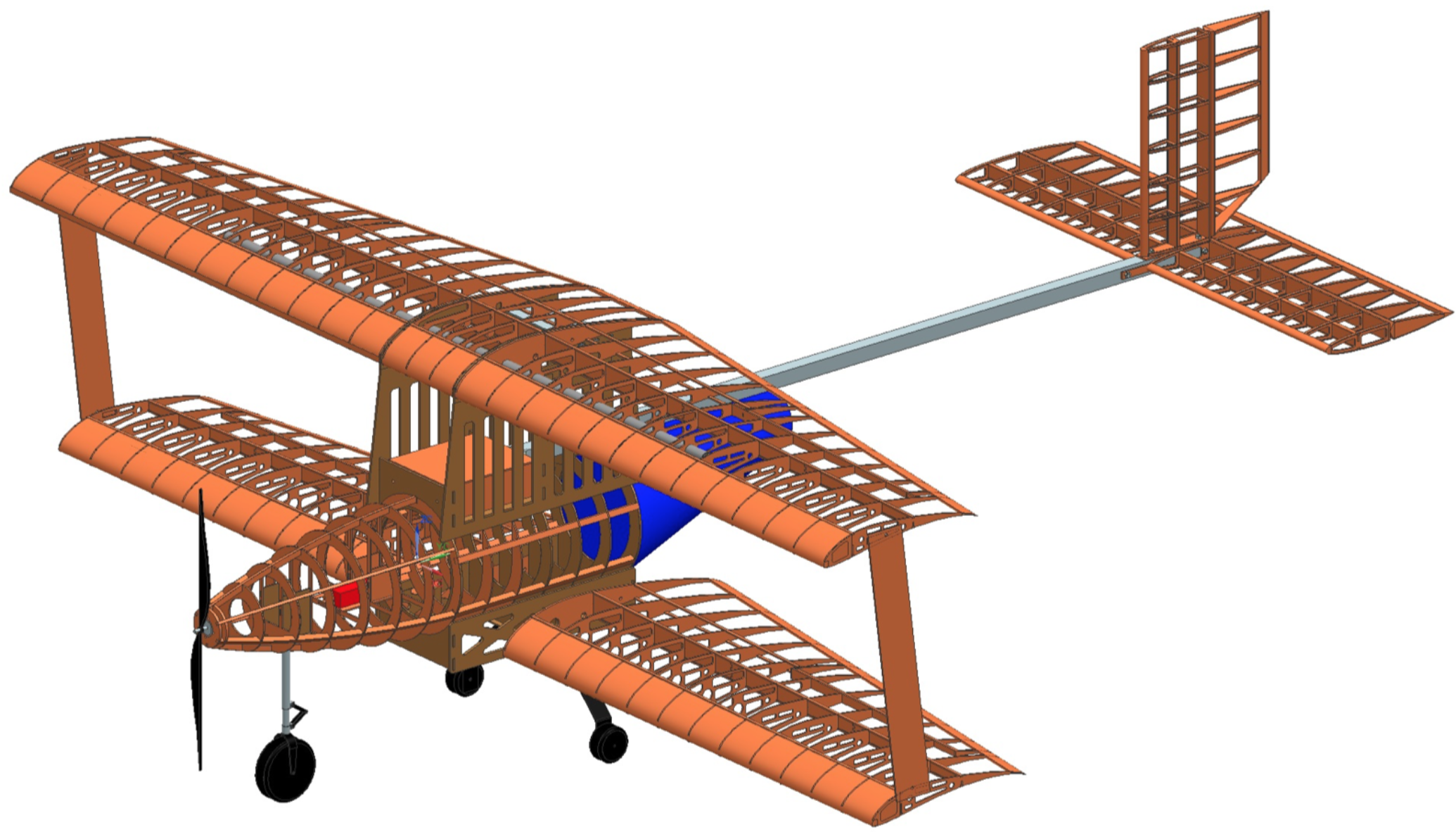
The M-12 is a bi-wing aircraft with its bottom wing positioned low, and its upper wing placed high above the fuselage and staggered forward of the bottom wing. Both wings utilize the Selig S1223 airfoil, and its planform and taper were designed to maximize payload weight capacity and to reduce wingspan given the maximum static thrust available. The conventional empennage layout was seleced to aid in manufacturability and due to weight savings over alternatives. The vertical and horizontal portions of the tail employ the NACA 0012 symmetric airfoil. A 199 Kv electric motor that produces 15.65 lbs of static thrust with its 24 in by 16 in wooden propeller is used along with a tricycle configured landing gear system.
Optimization and Sensitivity Analysis
Initial sizing of the M-12 was conducted based on data from past years, initial model estimations from AVL, as well as wingspan and configuration analysis. A biplane configuration was predicted to generate a higher flight score than a monoplane configuration. Further, sensitivity of the potential flight score was analyzed against the wingspan, and reached zero when the wingspan is 8.5 ft, maximizing the M-12’s score. The M-12 was then optimized through trade studies and performance analysis on each design variation, as shown below.
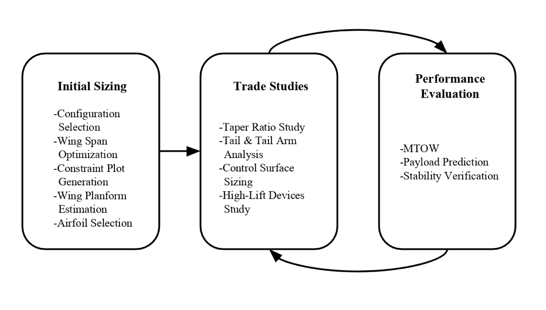 Optimization process of the M-12.
Design Features & Details
Airfoil Selection
Around 30 high-lift airfoils were selected from Airfoil Tools and considered for the M-12. Out of them, three airfoils were selected to be the final candidates for the M-12. These were compared with their Clmax, L/Dmax and stall angle as shown in Table 1. Each airfoil was put into the team’s takeoff prediction code and analyzed with the other conditions set constant. The S1223 airfoil was found to require the shortest takeoff distance and was thus picked as the airfoil for the M-12.
 Characteristics of three candidate airfoils at Reynolds number of 500000. The selected airfoil is highlighted.
Configuration & Wing Design
A top view of an M-12 wing is shown below, and the parameters of it are summarized in the table below.
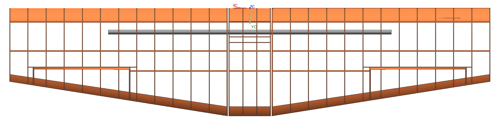 Structural layout consists of a basic rib and spar configuration.
 M-12 Wing Parameters (for a single wing).
The high-lift and short runway requirements encouraged the team to consider a biplane configuration for the M-12. Since the wingspan is also involved in the scoring equation, a scoring analysis was conducted for both the monoplane and biplane configurations at different wingspans. The analysis was based on the planform area determined from the chosen design point of the constraint plot shown later, and the results are shown below, which indicates that the M-12 will achieve the highest score at 8.5 ft wingspan with a biplane configuration.
 Scoring analysis of the M-12 for both the monoplane and biplane configurations.
The team then analyzed stagger, taper, twist and incidence angle of the wings using AVL. A stagger of 0.1 m between the top and bottom wing was found to maximize the lift coefficient through AVL analysis and was thus chosen for the M-12. Trade studies were then performed on taper ratio and taper start position. In order to maximize the lift coefficient, L/D, and efficiency while maintaining a manufacturable chord size, the taper ratio was chosen to be 0.70 and begins adjacent to the fuselage. As sweep would only be beneficial for flight at the transonic regime, it was ruled out due to the aircraft’s low expected flight Mach Number. Geometric twist was not considered for ease of manufacturability.
The control surfaces were sized using the team’s historical data and a trade study at the banked turn stage. In order to achieve small aileron deflection, the team selected ailerons located from 50% to 90% of the half span, while occupying about 30% of the chord on average. Ailerons were designed on both sets of wings and are controlled separately to allow for aileron differential that reduces yawing moments generated by the ailerons.
Empennage
The conventional tail and the T-tail configurations were considered for the M-12. The conventional tail is advantageous due to its historical credibility, ease of manufacturing, lighter structural weight and because it is less affected by wing wake, while the T-tail could reduce downwash on the horizontal stabilizer due to the biplane configuration. After comparison from simulations in AVL, the two types of tails were found to provide similar performances on efficiency, L/D, and control surface deflection. In order to achieve better manufacturability and weight savings, the conventional tail was chosen for the M-12 over the T-tail.
Trade studies were then performed on the empennage sizing in order to obtain the most efficient configuration. The tail boom length was chosen to be 4.65 ft to provide a large enough rotation angle of 17.5 degrees. Based on historical tail volume coefficients on the team, the horizontal and vertical stabilizers were sized using the tail coefficient method. Both stabilizers are untapered and unswept for ease of manufacturing.
The elevator and rudder are both 50% of the chord and span the length of their respective stabilizer. The tail has an incidence angle of 2 degrees to reduce the required control surface deflection for maneuvers.
Loads & Environments, Assumptions
Design Load Derivations
The maximum expected lift forces on the fuselage, wing, and empennage during flight and the maximum forces on the tail boom were analyzed using AVL. The load factor of the M-12 is plotted against its speed below.
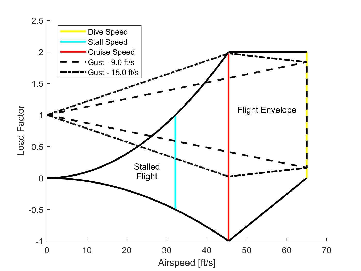 V-n Diagram of the M-12.
Environmental Considerations
The aircraft has a limited operational temperature based on the ratings of the ESC and Li-Po battery as well as air density, which is temperature-dependent and impacts maximum payload capacity. The M-12’s electronics are rated for 0°F to 113°F, and operating outside of this range incurs a power drop of around 50%. Analysis of historical weather data in Lakeland, Florida in early March leads the team to expect a temperature range between 56°F and 82°F, which is firmly within the safe operating range for the electronics. The aircraft’s UltraCote covering will prevent structural and electronics damage in the presence of high humidity, fog, and/or light precipitation. Adhesive tape is used to seal hatches and attachment points to protect internal systems. Greater precipitation and other inclement weather may damage the electronics or compromise the structural integrity of the airframe. High winds are also a concern, and vertical gusts of up to 15 ft/s are taken into account in the flight envelope as shown in the figure above.
Performance Analysis
Flight & Maneuver Performance
The flight performance parameters of the M-12 are calculated and estimated by MATLAB and AVL, and the results are summarized in the table below.
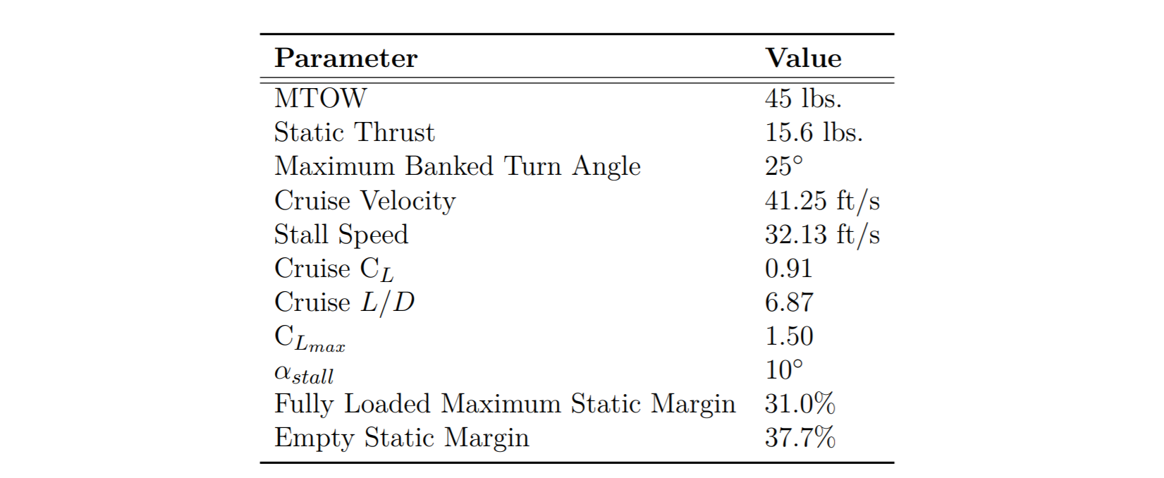 Flight performance parameters of the M-12.
The M-12 has a CLmax of 1.50, which occurs at a stall angle of 10 degrees. These values are determined by running AVL at trimmed cruise conditions and increasing the angle of attack until any section of the wing reaches a sectional lift coefficient greater than CLmax of the S1223 airfoil at the cruise Reynolds number of 500000. While the stall angle is rather low, the team is confident that the actual stall angle is higher based off historical data. Additionally, wing manufacturing can produce imperfections on the leading edge, which may trip the air flow to turbulent and in turn help delay separation and stall.
The drag polar of the M-12 was computed and constructed from AVL, as shown in the figure below. The cruise L/D was then extracted from the drag polar to be 6.87. The Oswald efficiency factor is estimated to be 0.65 at trimmed cruise condition.
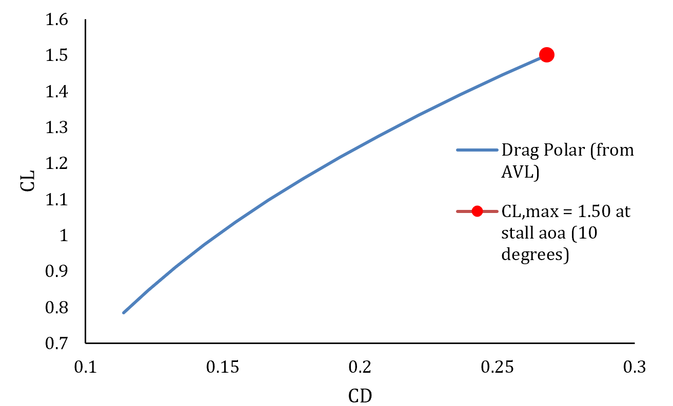 Drag polar of the M-12 constructed from AVL.
The Trefftz plot of the M-12 at trimmed cruise condition is shown in the figure below.
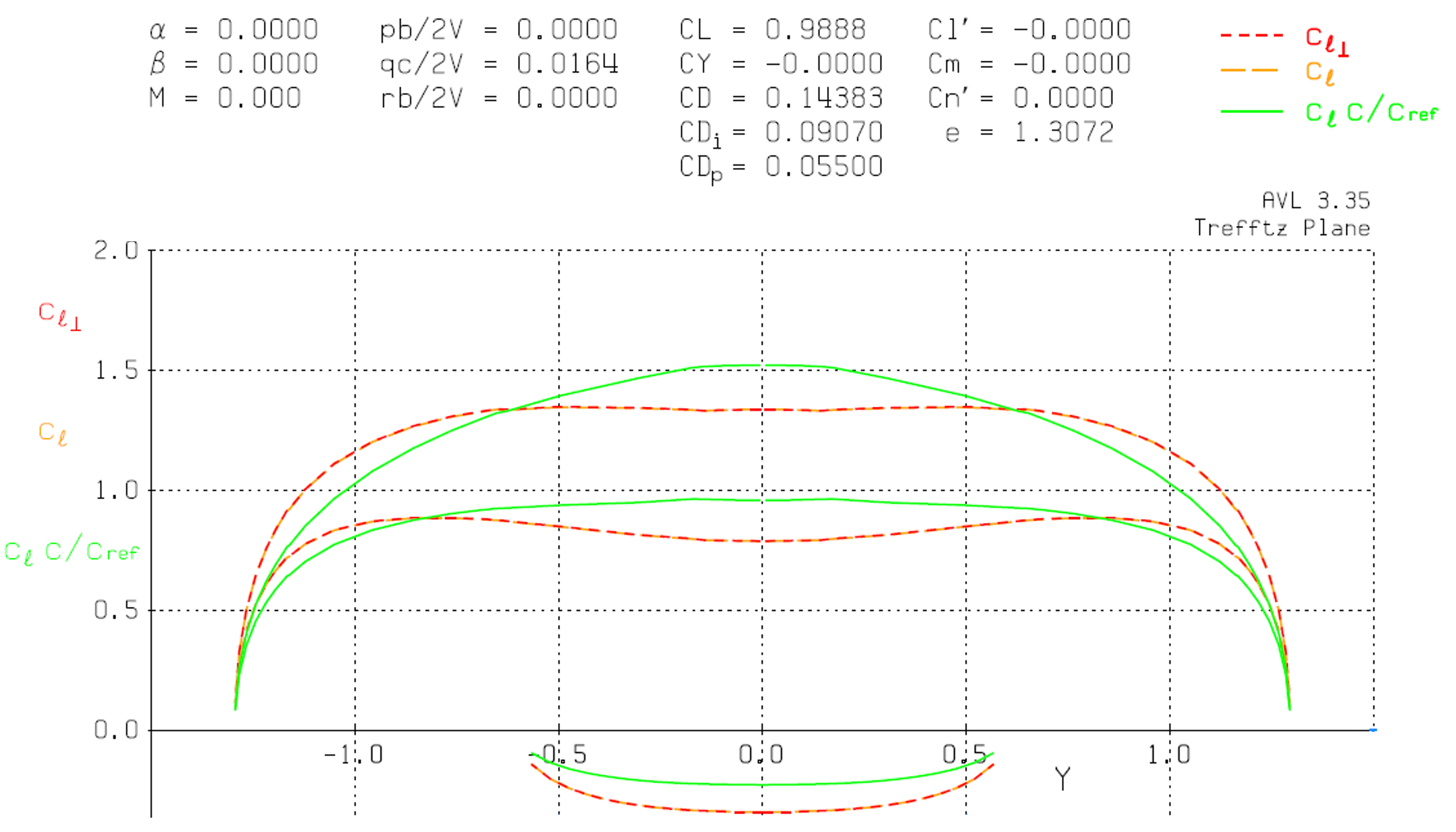 Trefftz plot of the M-12 at trimmed cruise condition.
The M-12 power requirement was calculated for various stages of flight to ensure that the aircraft is capable of completing a flight round at competition while carrying the maximum predicted payload. Weight, climb rate, air density, velocity, reference wing area, parasitic drag, induced drag factor, and bank angle in radians are taken into account to determine power requirements which were used to produce the operational flight envelope shown in the figure below. As shown in the figure, the M-12’s propulsion system provides necessary power to satisfy all major flight stages in its fully loaded configuration.
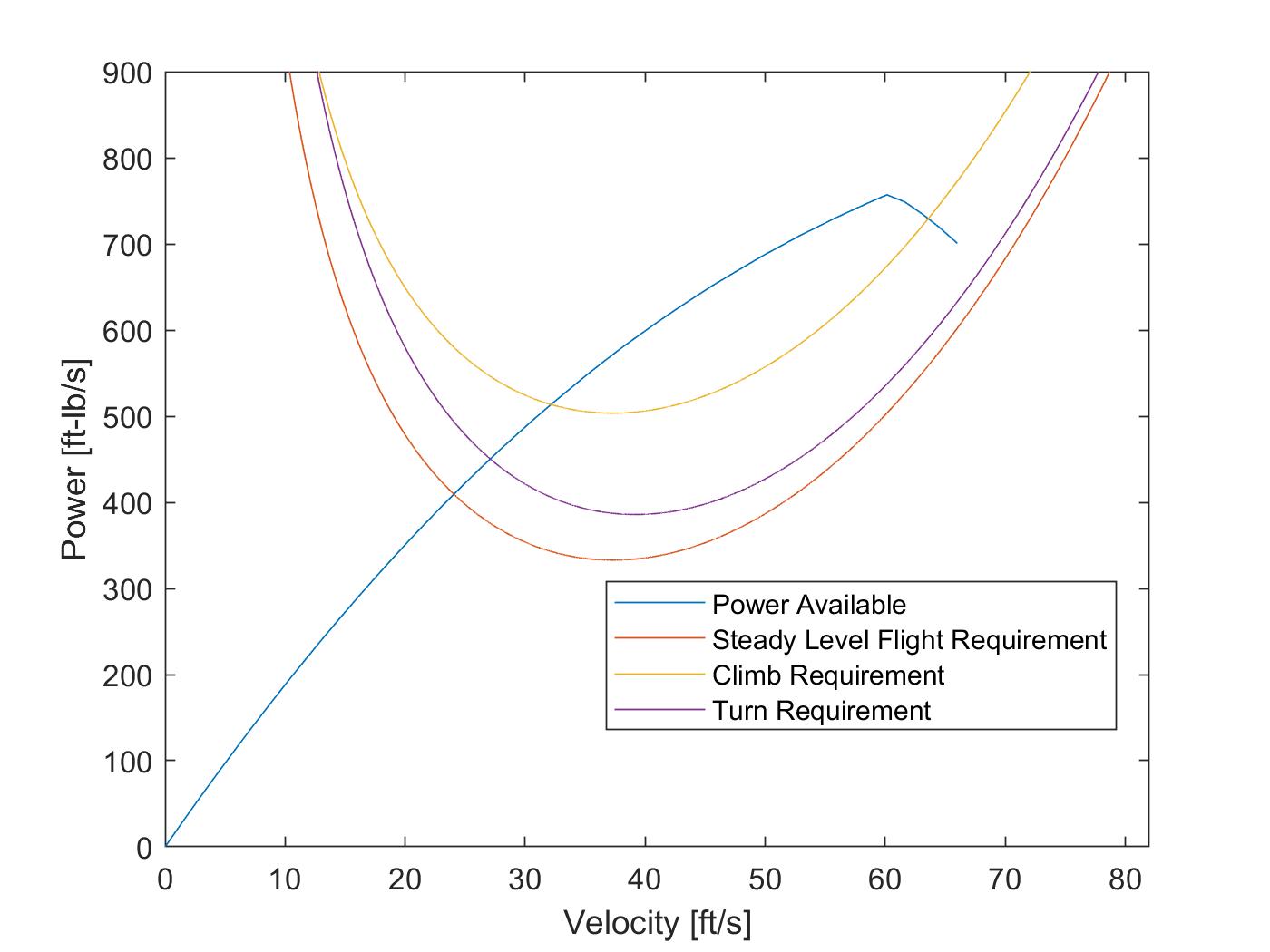 M-12 flight envelope
The thrust-to-weight ratio and wing loading constraints for stall, takeoff, climb, and cruise stages are shown in the following figure. It is indicated that the design point selected from preliminary sizing and subsequent system optimization satisfy the flight stage requirements.
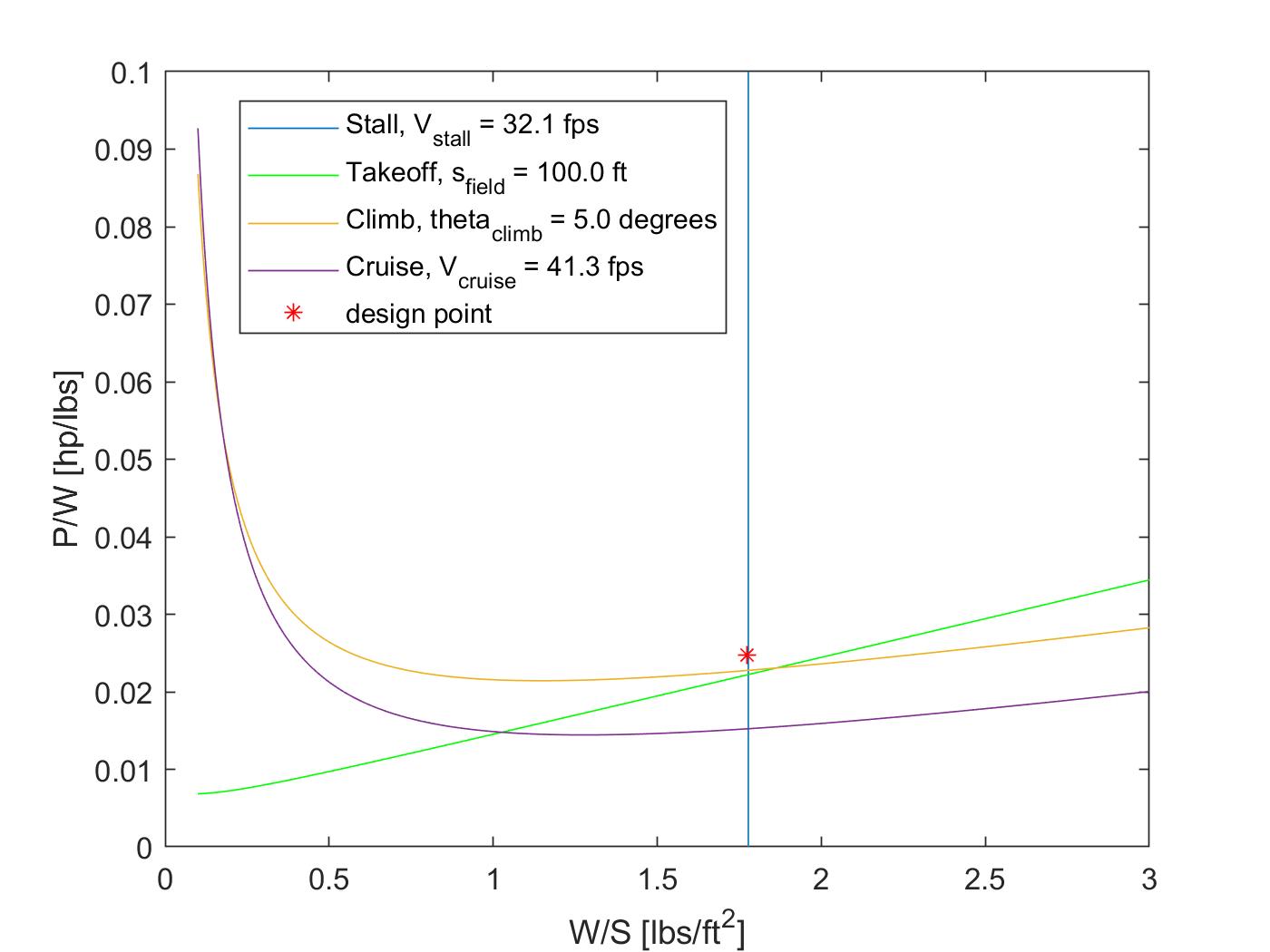 M-12 flight constraints
Dynamic & Static Stability
Stability was the priority for the M-12 design to ensure a safe flight. The empty weight static margin of the M-12 is 37.7% and the fully load static margin of it is 31%, which ensures the longitudinal stability of the plane during flights.
With the goal of achieving Level 1 dynamic stability in all modes as defined by the CooperHarper scale, the dynamic stability of the M-12 was also analyzed using AVL’s eigenmode analysis. Results are shown in the table below. M-Fly has historically found that AVL’s spiral mode is inaccurate as the team has not had trouble with spiral instability in the past, so the spiral mode was not considered here. Since the M-12 achieves Level 1 stability in all modes, pilot compensation would not be required to maintain steady level flight.
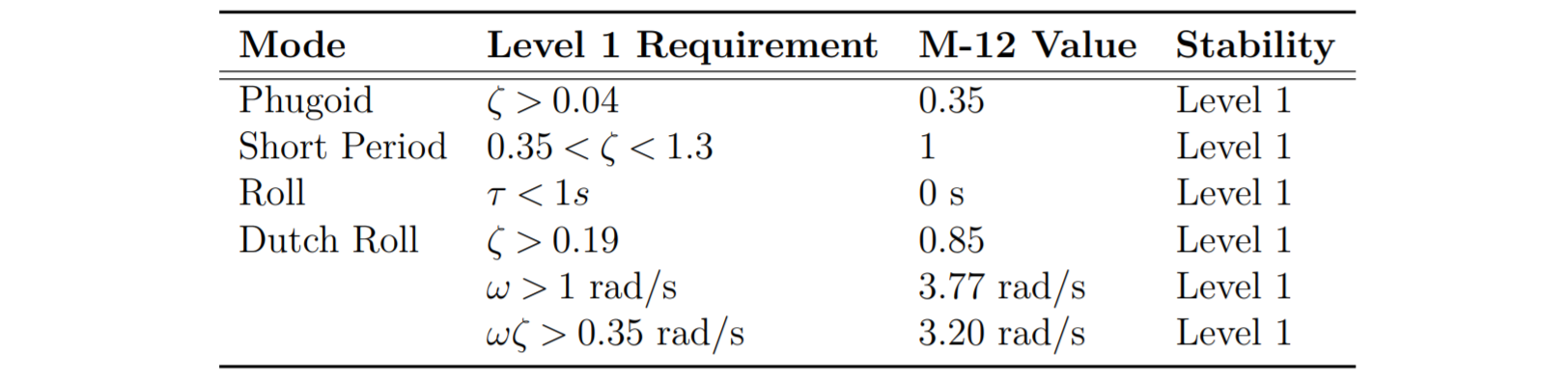 Dynamic stability of the M-12 with its fully loaded configuration.
Lifting Performance, Payload Prediction, and Margin
The lifting performance of the M-12 is presented in the payload prediction plot as shown below, taking into account density altitude, thrust, coefficient of lift and airspeed velocity. The M-12 was modeled at trimmed cruise stage at several density altitude conditions, and the lift performance was calculated by AVL. At sea level, the maximum expected payload is 22 lbs.
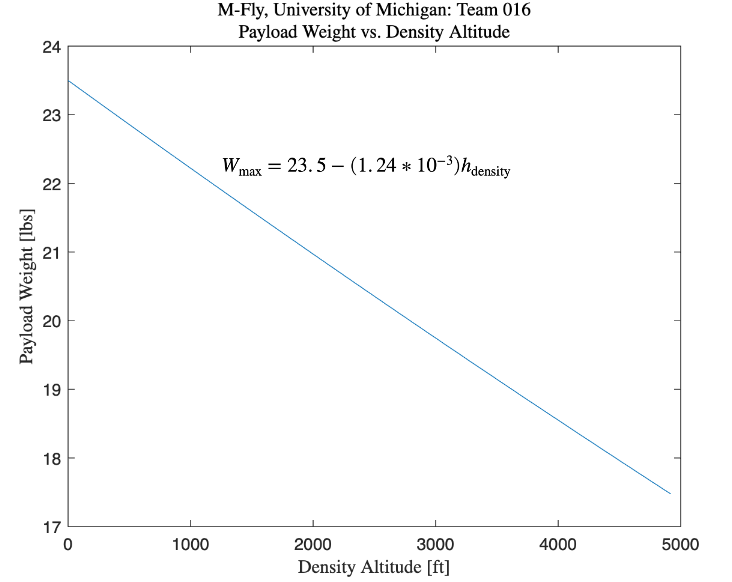 Payload Prediction Graph.
Conclusion
The M-12 is a bi-wing configured aircraft using a conventional tail that has been designed to place at the top of the 2020 SAE Aero Design East competition. The aircraft has the capacity to carry one spherical payload and up to 22 lbs of boxed steel payload, leading the team to believe it will be competitive in flight rounds and in other portions of the competition.
Although the M-12 eventually did not come to the top due to power losses of the propulsion system that could not be fixed during the competition, it successfully flew a few rounds in the air and proved the feasibility of our design.