This is a design and manufacturing project I conducted for the course ME 350 at the University of Michigan. My collaborators on this project are Holden Chevalier, Juevara Issa, Junjie Luo, and Avant Mehta.
Goal
The goal of project “ball sorting machine” is to design and build an efficient mechanism that uses a DC electric motor in a closed loop position control system to move a cup to the desired position and orientation accurately enough to catch each ball and drop it into different places based on the color of the ball.
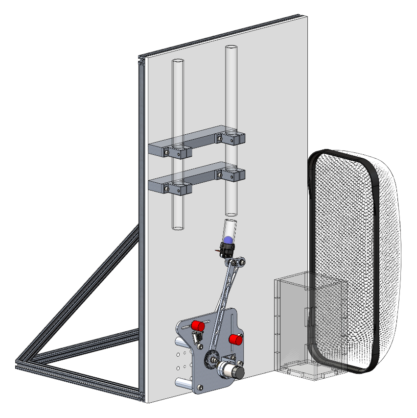 Layout of the arena and the designed ball sorting machine.
Design Process
During our process of design, we considered the location and orientation of the cup, the location of the ground pivots, the transmission angle, and power of the motor.
We first constructed a 2-D mechanism in Solidworks with concerns of the location and orientation of the cup, the location of the ground pivots, and the transmission angle. We generated a 2-D layout of the arena and three equivalent cups each with a support under it (the coupler is part of the support). We changed the location and orientation of the cups so that two of them could receive the balls dropped from each of the two chutes and the other one could throw the balls into the basket and the net. We then constructed two circles based on the corresponding two ends of the three couplers, the resulting centers of the circles were the location of the ground pivots. The ground pivots, however, should not be lower than the ground level. Therefore, we adjusted the location and orientation of the cups as well as the location of the ground pivots so that both the cups and the ground pivots met their individual requirements. Another concern was the transmission angle, it should be within the range of 30 to 150 degrees and be as close to 90 degrees as possible. Consequently, we fixed our ground pivots and checked how the transmission angle would change during our intended range of motion. Adjustments and improvements were made again so that all the three requirements were met.
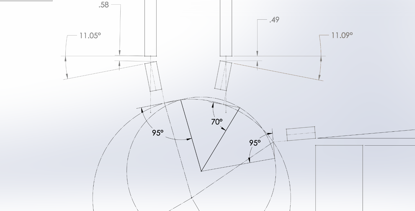 2-D mechanism constructed in Solidworks.
After finalizing our 2-D mechanism design, we further extended it into a 3-D model in Solidworks in order to verify its manufacturability and functionality. Furthermore, we imported this 3-D model into ADAMS to predict its behavior through simulation. In order to achieve the highest efficiency, we wanted the mechanism to travel with a certain acceleration profile. We used this profile and different time values to simulate our designs in ADAMS, determining the resulting power consumption.
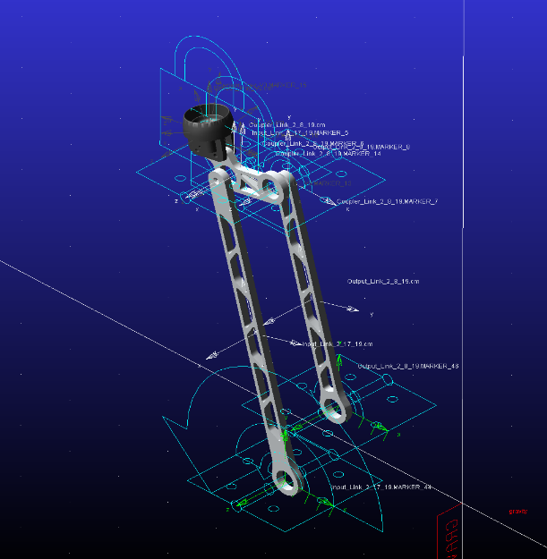 3-D mechanism constructed in ADAMS.
 ADAMS simulation result of the mechanism power consumption versus seconds.
Each of the team members completed the above steps and generated our individual designs. By using a Pugh Chart considering four aspects of our designs: the mass, the transmission angle deviation, the ball reception angle deviation, and the time required to complete a half cycle at a 1 W motor power restriction, we selected our final design, which is shown below:
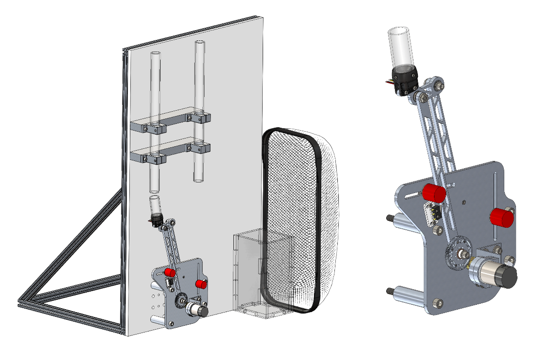 Isometric view of the mechanism.
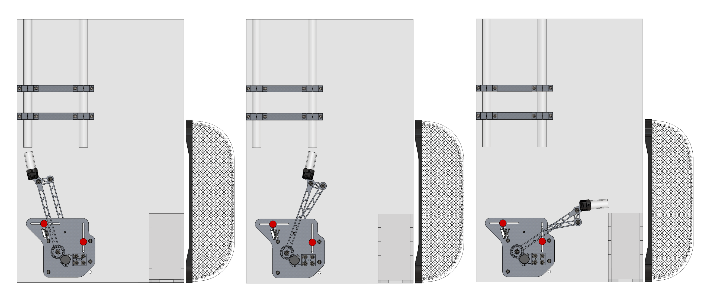 Final CAD of the mechanism at three critical positions.
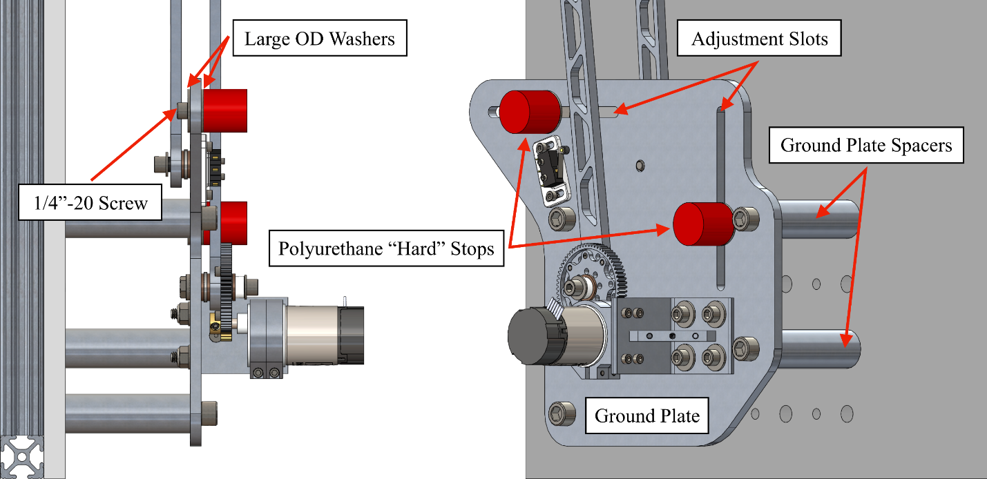 Side view (left) and isometric view (right) of ground link (plate) design.
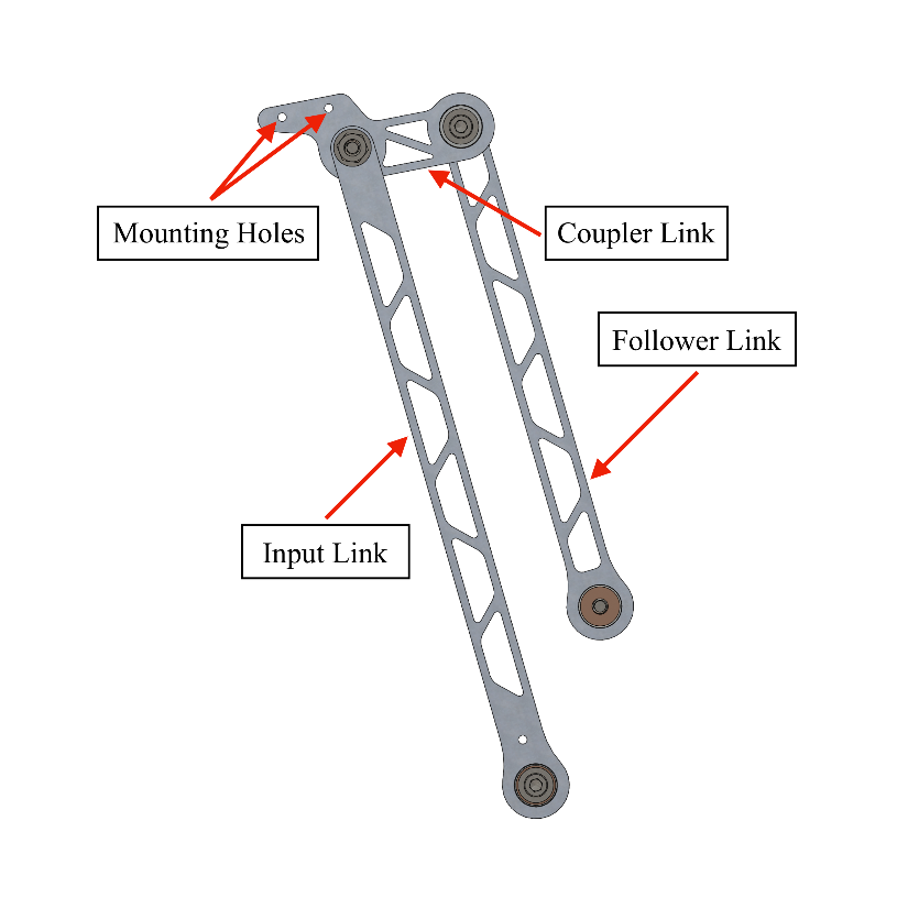 CAD of input, coupler and follower links.
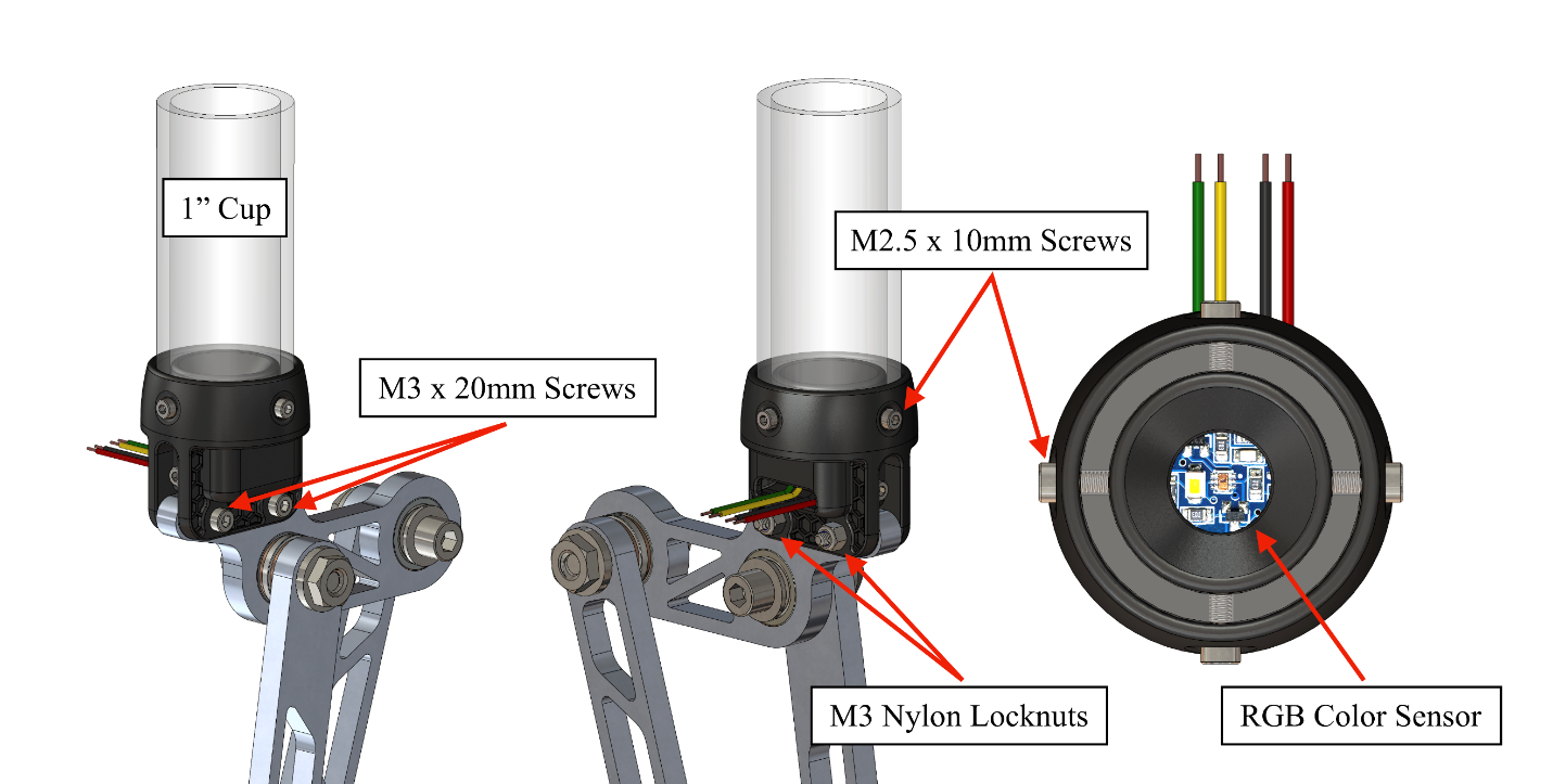 CAD of cup holder.
 CAD of cup holder tray.
The joint designs of the mechanism are shown below.
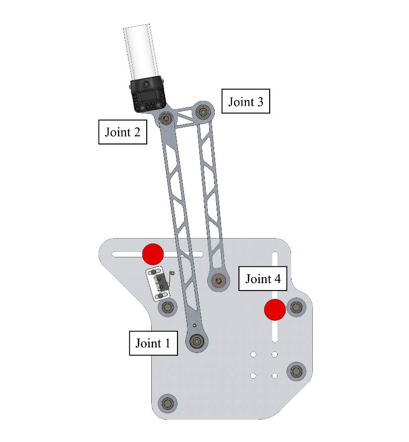 Picture of joint 1-4.
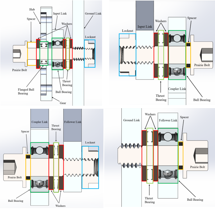 Cross section views of joint 1-4. Joint 4 was designed without locknut because otherwise the locknut will block the motion of input link.
Transmission Ratio and Type Determination
Transimission is critical for the DC motor to drive the mechanism. In order to determine a proper transmission ratio, we used three methods: inertia matching, gravity compensation, and cup resolution. After applying the three methods, we decided to select a final transmission ratio of N=2.667.
Another Pugh Chart was designed to select the proper transmission type. Eventually, gear drives were selected over belt drives and chain drives.
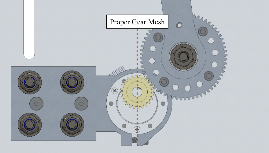
Our final transmission design features a combination of aluminum and hardened brass spur gears which transfer torque from the motor output shaft to the input link. The use of gears for the transmission minimizes potential losses in efficiency and accuracy, while maintaining a small overall footprint and reliable operation. An overview of our transmission design is illustrated below.
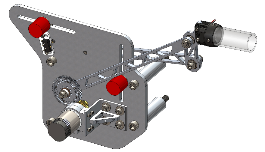 Isometric view of mechanism, including the transmission.
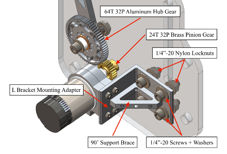 Motor rotation is in parallel with ground plate due to 90-degree motor mounting adapter.
The ring clamp motor mounts are chosen for allowing a large amount of adjustability and fine-tuning of our gear engagement. Due to the ring clamp’s relatively shallow width, we chose to use (2x) in combination with a 90 degrees support brace for the L-bracket to eliminate any possible movement of the motor. The 1” wide contact area of both 37mm ring clamp mounts provides more than enough friction and clamping force to keep the motor stationary during operation of the mechanism. To provide maximum adjustability, the off-center motor shaft was designed to be orientated at its highest theoretical position as seen below.
 Orientation of the metal gearmotor in relation to the ring clamp mounts.
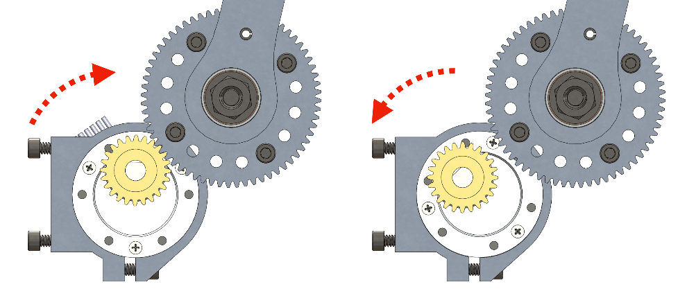 Radial adjustment of the gear engagement is accomplished by twisting the motor into proper alignment.
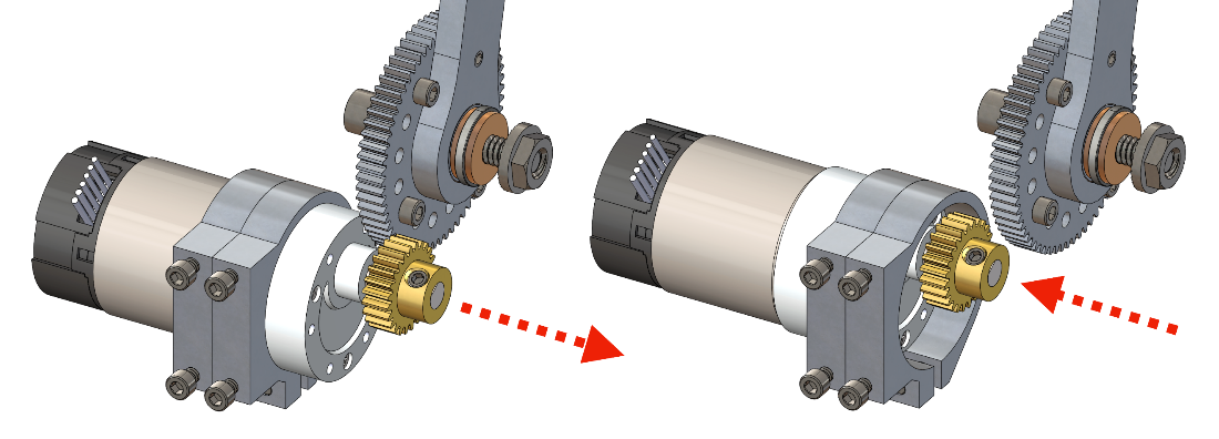 Axial adjustment of the gear engagement is accomplished by sliding the motor back and forth.
Sensors
The sensors used in this project include a 64 CPR two-channel Hall effect encoder, an Adafruit RGB Color Sensor, a Snap Action Switch (limit switch), and a Single Pole Single Throw (On - Off) Toggle Switch. These sensors work collaboratively with our Arduino Uno microcontroller board to achieve reliable and accurate control of our mechanism.
The encoder attached to the rotor of the motor is used for determining the angular position of our mechanism. It uses hall effect to provide a quadrature resolution of 64 counts per revolution of the rotor. Due to the 30:1 gear box of the motor and our gear’s transmission ratio of 2.67:1, the encoder provides 5126 counts per revolution on our input link, which gives a resolution of 0.07 degrees. This resolution was determined to be enough for our application of receiving and disposing balls.
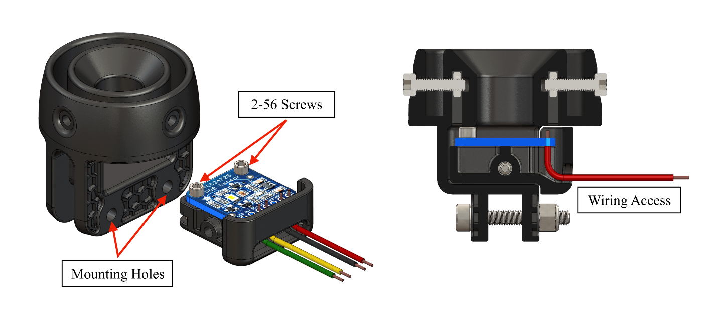
The Adafruit RGB Color Sensor is used for detecting the color of received balls and thus providing information to the Arduino Uno microcontroller board for the mechanism to proceed. The sensor shines white light to its front, senses the color reflected back to it, and assigns integer values ranging from 0 to 65535 for this color in four categories: red, green, blue, and clear. We obtained the corresponding values for different colors by experimentally testing the color sensor in the environment that it will operate within. Our cup holder was designed to be black and constrain the color sensor so that the color sensor will not be exposed to outside environment when the balls are dropped in (the color sensor will only face the ball and the black wall of the cup holder). Therefore, the impact of outside environment noise is limited and the reading of the color sensor will be relatively repeatable and reliable. Despite of this, there were still variations in the color sensor reading because of the heterogeneous color distribution on the balls. We resolved this problem by testing the readings of the sensor for each color multiple times and setting an appropriate range to accommodate the possible variations.
The Snap Action Switch (limit switch) is used for indicating the starting position of the mechanism and allowing the encoder to use it as a reference position. Although strikes of linkages are used for triggering it, since it is an electronic component, large forces may possibly damage it. Therefore, the limit switch itself can’t act as a hard stop, and it is placed next to the hard stop at the starting position. The limit switch only detects whether the circuit is connected or not, so it is not sensitive to noise.
The Single Pole Single Throw (On – Off) Toggle Switch is used for enabling human to directly control the on or off the motor. It will prevent undesired operation of motor and thus ensures safety. The toggle switch only detects whether the circuit is connected or not, so it is not sensitive to noise.
Controller Design
A combined feedforward (gravity compensation) and feedback (PID) control was implemented on the mechanism.
We combined physical testing and ADAMS simulation to quantify the effect of gravity on our mechanism. We applied a still motion on the leftmost and right most positions and obtained two values reflecting how much torque is required to hold our mechanism. Since our mechanism must be able to start its motion overcoming the gravity form both the leftmost and rightmost motion, this gravity compensation method is very important for the accuracy of our controller.
PID feedback control is also important to achieve a stable and efficient system. Due to the benefit of using state machines in our Arduino codes, we were allowed to test and tune the gains for each state individually. The result are shown below.
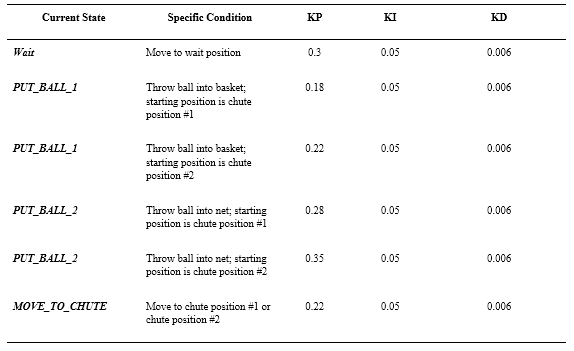 Summary of controller gains for different states. KP stands for the proportional gain, KI stands for the integral gain, and KD stands for the derivative gain.
Final Testing Results
After testing our mechanism many times, we need to assemble it to a real playing field for final testing. According to the rules, there are 5 minutes for us to setup the whole device. Since all the parts were assembled to the ground plate in advance, we just attached the ground plate to the playing field using four screws and four spacers. In the meantime, testing code was uploaded to the Arduino board using the provided computer and wires were connected to both the power supply and playing field. Finally, we reset the Arduino board and reported we were ready. This process was completed within the time limitation. Then the power of playing field and the toggle switch of our mechanism were turned on, the final testing started.
We needed to catch and sort 30 balls (including 8 blue balls, 7 maize balls, 8 red balls, and 7 white balls) in a time constraint of 2 minutes. Since the results of our tests before final testing were successful, we held high expectations to our mechanism. All the balls are expected to be caught and correctly sorted without any physical contacts to the mechanism. The whole running process was expected to be completed within 1 minute and 5 seconds.
We had three trials in our final testing. The detailed results of each trial is shown below.
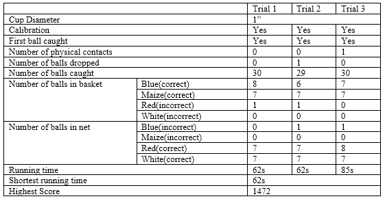 Final Testing results.
Although not all of the balls were sorted correctly, considering that the number of incorrectness is small, our mechanism still meets our expectation. The incorrectness is due to an incorrect color sensor reading rather than improper controller values since most balls were able to carry out required motion under the same controller gains. The reading problem may be resulted from our relatively narrow range of identifying the red and blue color. The problem may also be due to the fact that the specific red and blue balls don’t meet their general color standard since the same problem happened twice on these specific balls. Therefore, in the future, adjusting the color sensor code may be a large improvement we can make.